
- #Ip camera pinout wiring diagram how to
- #Ip camera pinout wiring diagram Patch
- #Ip camera pinout wiring diagram code
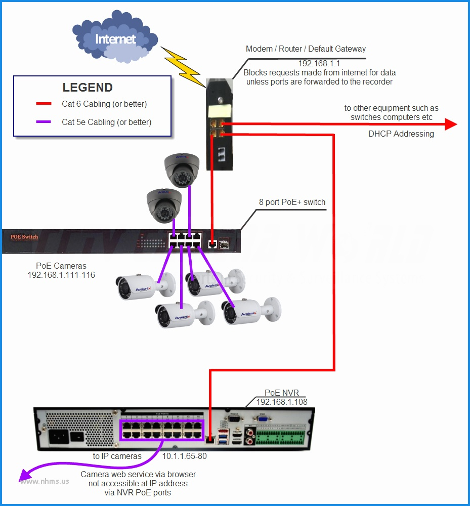
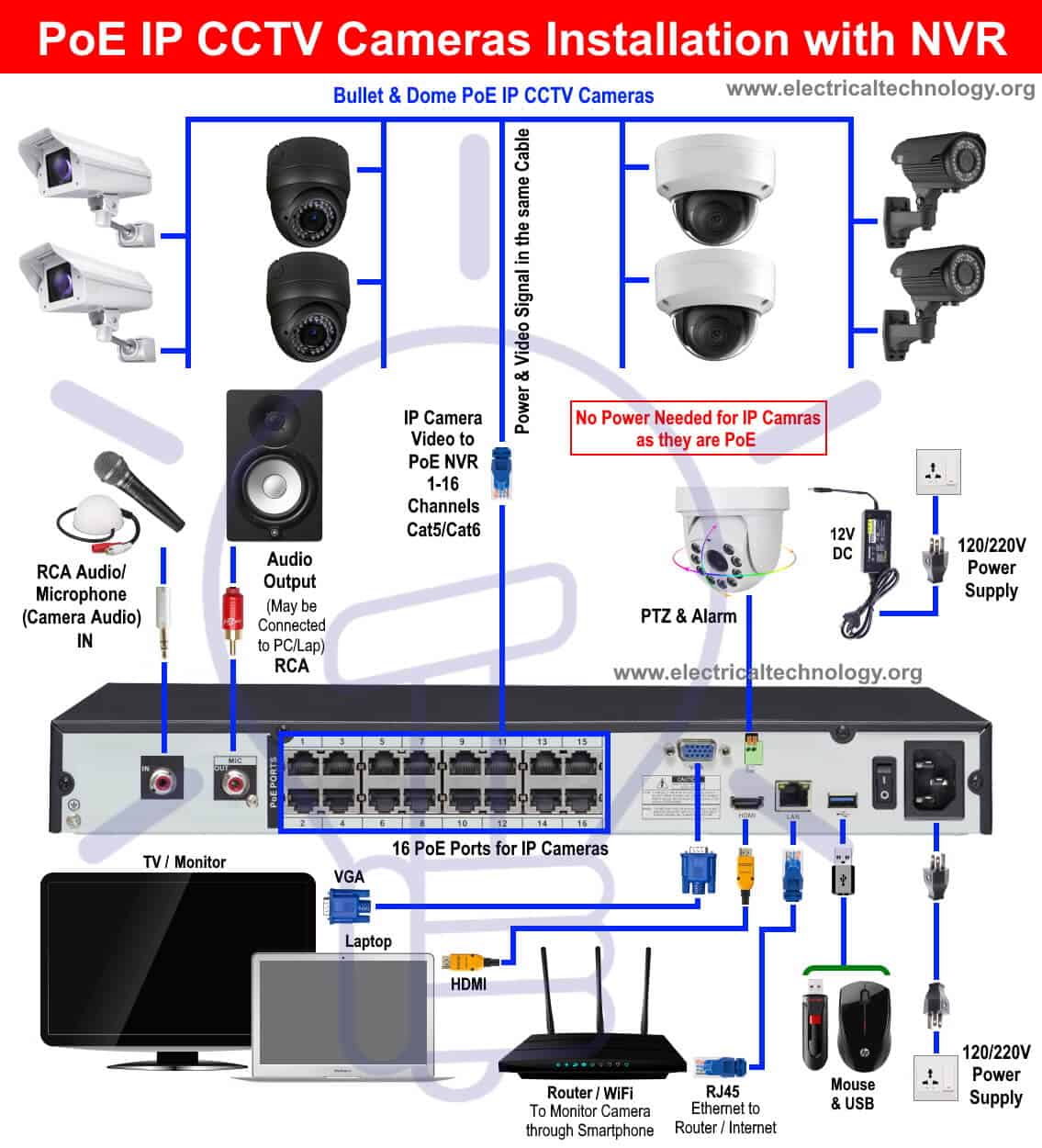
When wiring up an IP camera, or any other IP device for that matter, you must use network cable such as CAT 5e.
#Ip camera pinout wiring diagram how to
If you orient your Pi such that you are looking at the top with the GPIO on the right and HDMI port(s) on the left, your orientation will match Pinout. How to wire RJ45 plug for an IP CCTV Camera. Pin 1 is the only pin with a square solder pad, which may only be visible from the underside of your Pi. Pinout depicts pin 1 in the top left corner. VIP Vision IP Cameras use a specific wiring method with 6 wires, actual configuratio.
#Ip camera pinout wiring diagram code
I sure don't want to access any corporate secrets so i'll sign a non disclosure agreement and pledge my first born son as security.Pinout! The Raspberry Pi GPIO pinout guide. Rj45 Poe Wiring Diagram - Rj45 Wiring Diagram Poe / Dahua Ip Camera Color Code Pinout For The Here is the guide that shows you the color codes of dahua pinout, the dahua rj45 wiring diagram and which pin goes to which color wire to make a. Applies to: All Reolink cameras with the pigtail.
#Ip camera pinout wiring diagram Patch
So I tried to wire it the same as a patch cable only to discover the cable is not four twisted pair (green/greenwhite, brown/brownwhite, etc) but individual colors, brown, purple, yellow, green white, blue, grey, and orange. They said no because if customers knew the pin diagram then they would play with the jack and void their warranty. Pinout of power over ethernet (poe) and layout of 8 pin rj45 (8p8c) female connector and 8 pin rj45 (8p8c) male connectorpower over ethernet. Learn where to find wiring diagrams for your car. It means poe ip cameras are also known as power over ethernet cameras. So I called up Lorex asking for the pin diagram for the jack. They refer to the ones that get the power and transmit videos through. Nvr ip cctv camera connection om electrical work facebook diagram cameras poe injectors wifi bridges router and.

Cameras Wiring Diagram 1 Wireless Router 2 Onboard Computer 3 Ip Scientific. Camera Layout Schematic Cctv Network Example Security And Access Plans Electronic. I figured I'd just put a new RJ45 jack on, waterproof it well, be good to go. Want Cctv Camera Connection Setup Guide Here S How Zosi Blog. You may follow the wire order below to arrange the wires of your RJ45 connector. A couple of weeks after my one year warranty expired a second camera failed with the same symptoms. Applies to: All Reolink cameras with the pigtail cable. It was under warranty, sent it back, got a new one. The center two pins on the etnernet type jack connection on my lorex network camera model MCNB 2151 aka LNB 2151, got fried.


 0 kommentar(er)
